Tuesday, 21 January 2020

Cylinder Heads and Tyres

After another (very long) gap I have spent a few evenings working on the Beetle. In my last post I was cleaning the valves and considering getting the cylinder heads blasted to remove the carbon build up. In the end I used paint stripper to soften the carbon and then scraped it out. I had to repeat this process many times to remove the bulk of the carbon build up from the inlet ports. The following image shows the result. It's not perfect but it is definitely servicable.


I spent some time measuring the valves for wear - they seemed fine. The same cannot be said for the valve guides. The exhaust guides are well past their best and will need to be replaced. I'll do this by drilling the guide with an 8.5mm drill bit before tapping an M10 thread into them. Then I should be able to use a home grown puller to remove them - though that will be another post.

This evening I made I tyre bead breaker from three pieces of wood. This home spun tool worked fine on a wheel/tyre that had been joined since at least 1986. A couple of tyre levers ensured they finally parted company; see the following photographs.

The centre of the wheel above is supposed to be black, but the rim should be L680 Cumulus White (Kumulusweiss). There are also a few dings that need to be removed. That can wait for a future posting. However I cleaned the wheel and there was a lot more paint left than I thought.


Friday, 7 September 2018

Valve Cleaning

Firstly I should point out that I don't need my valves to be shiny, I just need them to be functional. Therefore I decided to give them a quick clean using a non-metallic scouring pad. To speed up the process I put the valve in my drill (I used a cardboard cuff to protect the valve stem from the chuck). The results aren't perfect by the valves look a lot better.


Wednesday, 5 September 2018

Restoration restart

It's been many years since my last post. I'm ashamed to say that I have made no progress in that time due to a combination of parenting duties and lethargy - mainly the latter. However last weekend my daughter headed off to University and so I thought I should give myself a kick.

When I last wrote I had split the crank case and was about to start cleaning. After lifting out the crank shaft and the distributor drive I noticed that the bottom of the fuel pump pedestal was still in the case. This is made of a hard plastic and it had split in two when the fuel pump was being removed. Removing this chunk of plastic turned out to be simple, but only after I'd watched this video.

I then set about stripping down the cylinder heads. I removed all the valve strings and then the valves. However the inlet valve for cylinder 1 did not slide out like the others. I had to use some 600 wet dry paper on the top of the valve before it would come out (to be safe I'll replace the valve and it must have been damaged in some way).

Tonight I started cleaning the cylinder head for cylinders 3 and 4. After a quick wash round with white spirit the top looked presentable and I could see no damage.


I then flipped the head over and started on the combustion chambers. Here's what they looked like before cleaning.

The combustion chambers themselves aren't bad however the inlet ports are full of carbon. Here's a close up of cylinder 4. Notice that there is barely any opening. I can only assume this engine was run with badly set valves for a long time. This is may be why the car was laid up in the first place.


I cleaned using WD40 and a non-metallic scouring pad (for cleaning pots and pans). This was the result. Notice that I've chipped some of the carbon away but there is still a lot to remove. I'm pondering whether to take both heads to be soda blasted.


I'll give the same treatment to the other cylinder head and then clean the valves.

Monday, 19 August 2013

Crankcase Split

A couple of posts ago I'd removed the oil pump from the crankcase. This was the last step before splitting the crankcase. I removed all the fasteners - there were many...


The bottom of this picture is the back of the engine (pulley) and the top is the front (flywheel). The small fasteners around the edge make the case oil tight and the six bolts in the middle ensure the crankshaft is secure.

I had the engine attached to my stand with three bolts - two in the left hand side and one in the right hand side. Before splitting the case the right hand side bolt was removed. I was pleased that the whole engine didn't fall on the ground at this point.

Next I worked round the case lightly hammering on a piece of wood to try and get the right hand case moving. Initially the only gap that appeared was at the old cooler. There was no sign of movement at the flywheel end at all. I noticed went round the seam removing any signs of sealant and sprayed liberally with WD40. I repeated the this hammering and spraying cycle a couple of times a few days apart - by which time the flywheel seam had opened about 0.5mm. Today I did the same again and the WD40 had clearly done its job as the right hand case came off almost immediately. The following photographs show each half.


The crankshaft and camshaft should simply lift out of the left hand case. Then I need to remove the oil pressure relief value and start the cleaning process. The plan is to start on the right hand side by scraping out the bulk of the joilly before bathing the case in solvent (probably white spirit as it's reasonably cheap). I'll then repeat as often as necessary and blow compressed air through the oil channels. Then repeat on the other side. In my future I see many trips to the dump with cans full of an unpleasant smelling black liquid.

Sunday, 18 August 2013

Carburettor Rebuild

The carburettor rebuild was pretty straight forward. I didn't remove either throttle as they both moved easily. However I did spend a lot of time withe carburettor cleaner removing all the black deposits that had built up over the years - as shown on the following images.


The final photograph shows all the rust and sediment that had collected in the float chamber. This was actually quite difficult to shift, I had to resort to scraping it off with a screwdriver. Another area that was particularly cruddy was the chamber the accelerator diaphragm covers. It looked like some sort of reaction had taken place but after a bit of scraping it turned out to be much worse than it looked. Importantly the sealing surface was smooth and so I don't think it will leak fuel (though only time will tell). 

After thoroughly cleaning everything I checked that all the channels and tubes were clear using compressed air. Then I put everything back together with new diaphragms, gaskets etc. The following shots show the final result - not gleaming but quite acceptable.


Wednesday, 31 July 2013

Carburettor Cleaning and More Joilly

Due to my summer holiday and the Glasgow Fair I have not got round to taking the axle shaft in for machining. Instead I have busied myself with some of the loose ends (of which there are many). The Solex 30 PICT-2 carburettor has been sitting in a sealed black back since it was removed from the engine. Last night I decided to clean the gunk that had accumulated on it over the past 45 years. The shots below show before and after the first pass of cleaning (using a toothbrush and some solvent).

Before 

After first clean
I was surprised at how easily the bulk of the grim came off. There are, of course, many pockets of dirt remaining but I'll probably deal with those during the strip-down.

Tonight I decided to return to dismantling the engine. It has been sitting under a blue sheet for many months and I was pleased to see it was still under there when I looked (and without any resident mice). The oil pump had been the stumbling block when I last worked on the engine. I had failed to prise it out of the case due to the lack of leverage (due to an absence of lugs or overhangs on the pump itself).

Although the case cannot be split with the oil pump in place (as the pump forms a bridge between four studs - two in one half of the case and two in the other half) I decided to loosen all the case fasteners to reduce the clamping effect on the pump. There are a large number of fasteners - though I didn't count them. They come in two sizes. There are small nuts (on a combination of studs and bolts) around the edge of the cases - presumably to keep everything oil tight. On the right side there are six large nuts on long studs - I assume these deal with the engine forces. Once I had loosened all these fasteners the oil pump did show some signs of movement and after 5 minutes jiggling with my bare hands the pump was free. The image below shows the rather unpleasant site inside the case.

Jolly Joilly
The pump doesn't look too bad, but I will need to read up on how to test its serviceability. Here's a picture of it and its sheen of joilly - clearly all that shines is not gold...
Back of the oil pump

Monday, 24 June 2013

The Right Tool

At the end of my last post all that was standing between me an the removal of the axle shaft was a rather large circlip. I had probably wasted about 45 minutes trying to extract it using a cheap set of circlip pliers. I am now the proud owner of  a better pair of circlip pliers - namely the Knipex 44 11 J3 (pictured below).


 It turns out these were the right tool for the job. Extracting the problematic circlip took all of fifteen seconds (and ten of those were spent getting myself into the correct position). Here is the the proof...


Next time I'll be reporting on whether or not the axle shaft could be machined for a reasonable amount of money or whether I needed to splash out for a new one.

Monday, 17 June 2013

Hitting Rewind

After many months of sitting on my thumbs I finally did some more work on the Beetle. At the time of the last posting I had failed to fit the brake drum and had decided to either replace the axle shaft (or have the existing one machined).

So axle shaft removal was the order of the day. My worry was that the wheel bearing I had previously hammered into place would be impossible to remove. I also wanted to avoid damaging the new wheel bearing (see Doing the Unstuck). Therefore the plan was to use the puller on the axle tube to remove the bearing.

The first task was to remove the three bolts that held the axle tube to the spring plate. The top two bolts came off relatively easily. However the lower bolt would not move at all. In the end I had to resort to the hack saw.

Next there are six bolts which hold the suspension tube to the gearbox. All six loosened with ease but three of them were taking their stud with them. Of course "sods law" applied and so the lowest bolt was one of these and the stud fouled the lower chassis leg which meant it could not be removed. The fix for this was to put the jack under the gearbox, remove the two massive bolts that held it in place and carefully raise the gearbox by about 1cm. Once this had been done the lowest stud had just enough room to be removed. I then spend 15 mins removing the three problematic bolts from their studs (this is done by tightening two bolts together on the stud and then using that and a couple of spanners to loosen the offending bolt) before cleaning the studs and screwing them back into the gearbox.


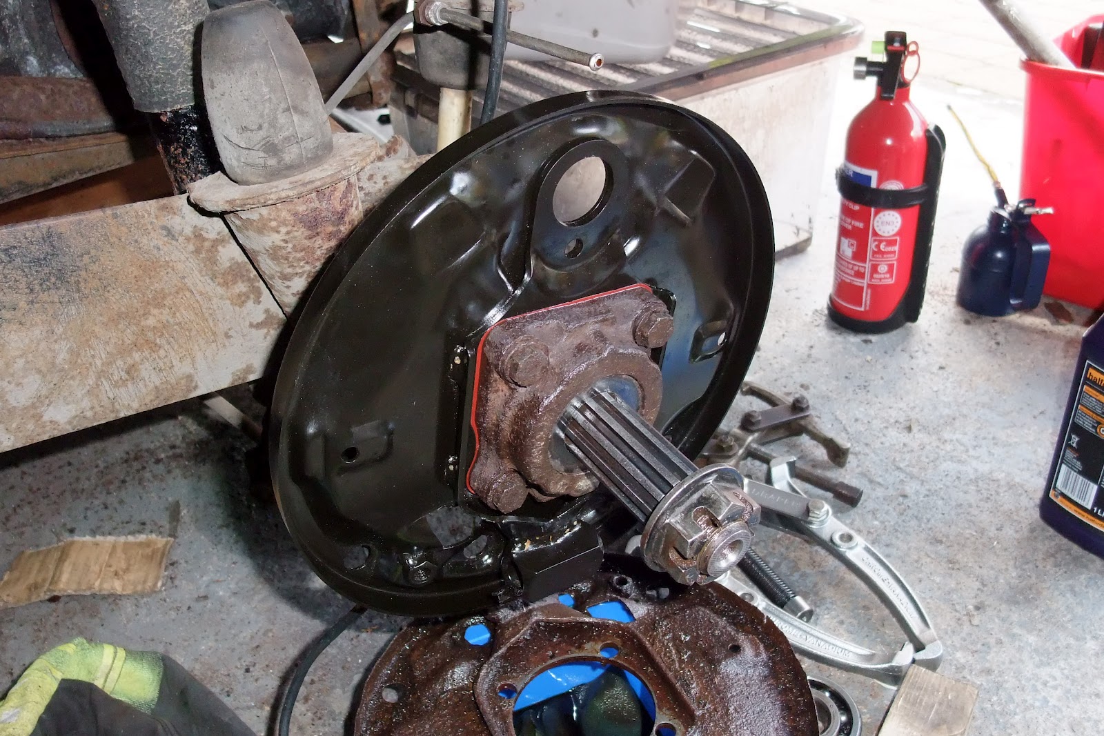
Next, the bearing housing and brake back plate were removed - leaving the outer spacer and bearing visible. The puller was then used (behind the bearing housing) to draw the suspension tube away from the gearbox complete with bearing and both inner and outer spacers. Once it had been drawn a few inches everything was loose enough to remove by hand.


The image above shows the suspension tube in situ after the bearing and spacers had been removed. Here's a shot of the removed suspension tube:


This is how things look after the suspension tube had been removed - only the axle shaft remains:


The final task was to remove the axle shaft which was "only" held in place by a large circlip. It can be seen more clearly in the next picture. It's a bit of a monster and I did not have a pair of pliers that were up to the job. I purchased a cheap 10" circlip plier set (Clarke CHT686) but they were not strong enough and warped under the load (they did bounce back to the correct shape though - so they may well come in handy for other, less strenuous, jobs later). Anyway, here's a picture of my current nemesis...


Sunday, 6 January 2013

Back Pedalling

In my last post I said the next task was fitting the brake shoes and drums. This is a simple matter of attaching the handbrake level to the rear shoe and then joining it to the front shoe with a spacer and spring. Here's what you're left with:


This is then attached to the backplate by sliding it onto the brake cylinder (from below), and placing the bottom into the adjusters. The shoes are then secured using the retaining springs. Finally the lower return spring is attached before hooking the handbrake cable to the handbrake level. Once this has been done, your brakes should look like this:


The drum can then be offered up to the shaft and bolted in place (though the bolt cannot be tightened fully until the wheels are fitted and back on terra firma). Looks nice doesn't it:


So that's the drivers side finished. Unfortunately the passenger side didn't go quite so smoothly... The drum only went this far on using my rubber mallet.


At this point I had two choices. The first was to spend the next twenty minutes hammer the drum home with the certain knowledge that future access to the brake shoes etc was going to be very hard/impossible (see my earlier posts). My second option was to remove the offending axle shaft and either have it machined to the correct diameter or to replace it with a new one (which presumably would have the correct diameter). Being naturally cautious I have gone for the second option.

Thursday, 3 January 2013

Rear Brakes (Almost) On

It has rained a lot in Scotland this year. In fact I think it has been raining more or less permanently since my last post. I know it is no excuse for not working on a garaged Beetle project... but it is the excuse I have decided to use and I will stick to it. However I am immediately going to contradict my chosen excuse when I point out that today, despite the rain, I headed out to the garage to fit the rear brakes.

On the passenger side the brake cylinder was bolted to the backplate as was the handbrake cable. Then on both sides the brake "star" adjusters were fitted. These where a much tighter fit than I expected - however with a bit of jiggling and tapping they seated correctly and still turned without the need for excessive force. The bolts were then coated with copper ease before being screwed all the way into the "star" adjusters. This is what I was left with:

I spent the rest of my two hour stint cleaning up the old spacers and handbrake arm in preparation for fitting to the new brake shoes. The next job will be to fit the new shoes and the new brake drums! The final job on the rear axle will then be to fit the new rubber gaiters and replace the oil.

Sunday, 22 July 2012

Front Wings Off

Theoretically removal of the front wings is very straight forward as they are simply bolted onto the shell (via captive nuts welded to the shell). Before this can be done it is necessary to remove the front bumper, indicators and headlights.

The bumper is attached to the shell with six bolts which were very simple to remove. The indicators have captive bolts which sheared off when I attempted to loosen the nuts. Use of heat was not an option because of the rubber bush and plastic lens. On reflection I should have tried a bolt splitter (or soaked longer with oil). The headlights are attached with a single screw at the bottom of the unit. Once removed the headlight simply unclips from the wing. Here is a picture of one of the headlight units dangling:


The unit is free once the spade connectors and the black socket have been unhooked. Initially I was puzzled by the fact that the black socket is too large to fit through the hole in the wing. However the connectors can be removed from the socket by depressing the small lugs (if that's the correct term) with a small screwdriver. Once this has been done the wires fit through quite easily. It's a good idea to immediately reassemble the socket immediately.

In the run up to this job I had soaked the wing bolts in penetrating oil from inside the boot. This meant that the majority of the bolts undid quite easily. The exception being the bolt at the bottom of the A-post. On both sides the captive nut immediately started to spin. I'll need to think about how best to fix this (the drivers side should be fine as I need to patch the bottom of the A-post anyway). Here is a photograph showing what I was left with (notice that the extent of the historical repair to the shell is quite clear in this photo):


Sunday, 10 June 2012

A Gallon of Purest Smetrol

This weekend my plan was to finish the rear axle. However I hadn't got round to buying a suitable sealant for the split gaiters. Therefore I decided to remove the petrol tank because it's clear that the body shell requires some welding and I don't want any explosions spoiling my day. There isn't much to removing the tank as it's held in by only four bolts. After these had been removed all that was needed was a bit of jiggling to lift the tank up. This gave access to the fuel line which was clamped  before cutting. Here's a picture of the tank after extraction.

And this is the gaping hole where it used to sit. Notice that there was a lot of work done in this area before the car was laid up. It's not very neat but unless it turns out to be full of filler it appears solid.

The front apron (if that's the correct name for the panel) is clearly for an older left hand drive car. I know this because the steering box access hole is on the wrong side and the panel also has holes for bumper brackets (whereas the bumper brackets for this model come through the wings instead).

The tank was half full of petrol that dated from about 1985. I released the clamp from the fuel line and nothing happened. After a couple of minutes a small blob of gunk appeared but there was no further movement. Therefore I opted for pouring the petrol out through the filler pipe - here's what I got.

This neither looked nor smelled like petrol. In fact it had a very odd sweet odour which caused me to name it "smetrol" (I was going to call it "shitrol" but that isn't as child friendly). Regardless it would seem that I have  a couple of gallons of premium quality smetrol - I wonder if anyone would buy it from me...

Monday, 4 June 2012

Painting...

It definitely seems premature, but I actually needed to get some painting done on the Beetle today. The old swing axle gaiters were removed in a few minutes thanks to my stanley knife. However the tubes were too rusty to make an oil proof joint with the new gaiters - see below:


Therefore I decided a bit of painting was in order. I decided to try POR-15 as it seemed to get quite a lot of praise in the various forum articles I'd read. I ordered a tester kit from Frost. This kit comes with some marine clean (a degreaser), prep and ready (an etch primer) and a small tin of POR-15. Application is pretty straightforward but a tad fiddly with the components still on the car. The picture below shows the tubes after POR-15 has been applied. It gives a very smooth finish - it feels very like glass. It's best to overcoat when it's tacky. If it becomes completely cured then it needs to be rubbed down before the next coat is applied.


Notice also that the sound deadening has been removed and the original colour of the car can be seen quite clearly. It looks like the right had engine bay panel needs replacing and also both bumper mount panels. Time to learn how to weld...

Anyway, back to the painting. After two coats of POR-15 I risked top coating with Frost chassis black. I'll see tomorrow if applying this directly to the tacky POR-15 was a mistake or not. It certainly seemed to get a good grip and there didn't appear to be any reaction - time will tell. Here's what the axle tubes looked like after their first coat - ooh shiny!


Sunday, 22 April 2012

Second Oil Seal Fitted

Despite having to fix an overflowing cold water tank I still managed to get an hour of work done on the beetle. This time I was fitting the new wheel bearing, brake back plate and oil seal. On the other side of the car the wheel bearing simply slid into place. However on this side it stuck before getting to the end of the splines. Judging from the manuals this isn't unusual. The solution is to drift it on with a suitable pipe or a punch. I opted for the latter and after 10 minutes solid tapping the bearing was seated. The next goes a shim washer and small o-ring. Then the back plate and paper gasket followed by the large o-ring. Finally the outer spacer is oiled and fitted to the oil seal (which had already been tapped into the housing) before the housing is bolted on. Here's the finished article.

The next task is to replace the oil gaiters on the swing axles as these have perished and torn. Once that job has been completed the rear axle should be oil tight!

Sunday, 15 April 2012

Doing the Unstuck

It may seem like I have forgotten all about this restoration blog but that is not true. The problem has been lack of progress and spare time. However this weekend I managed to spend a few hours in the garage. The plan was to remove the rear wheel bearing. Earlier attempts had involved hammering, heat etc. The ideal solution would be to use a puller. However it was not possible because there was no clearance at the back of the bearing for the puller arms. Therefore the plan was to use the grinder to cut a couple of slots on the outside of the bearing. These slots would then locate the puller arms. This was a bit of a fiddly job as the bearing kept spinning when the grinder was applied (I suppose that is what bearing tend to do). Finally I managed to get a couple of half decent slots opposite each other - one is visible below:

Then I held the puller arms in place as Fiona did the spanner work and the bearing started to move slightly. Once we  had moved it an inch it was possible to fit the puller arms behind the bearing and progress was much quicker.

Next time I'll be fitting the new backplate, bearing and oil seals. Then its time for the axle gaiters before finally fitting the new rear brakes and drums!